(updated 2-26-6 with clarification about ouput positive feedback, prompted from Achim Dassow)
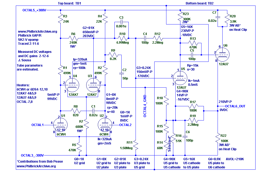
I hand traced the SK2-V schematic and captured it with Linear Technology's free SwitcherCAD.
If you like, you can download the SK2-V switcherCAD schematic.
Note that positive feedback is used at the front end to realize a second stage gain G2=81X, and at the output, to much greater effect, to realize gain G4=90X from the grid of U5 to the Cathode of U5. Without positive feedback from the cathode of U6 to the cathode of U5, the gain from the grid of U5 to the cathode of U5 would be the usual slightly less than 1, and the gain from the cathode of U5 to the plate of U6 would be around 0.3 as the external cathode resistance is about 40k and the internal plate resistance is about 15k. Claiming a large gain from a grid to a cathode of the same tube is a bit disconcerting, but that is just what happens when pfb is added. The swing at the cathode is indeed much larger than the swing at the grid.
One way to appreciate the contribution of positive feedback around U5, through U6, is to think that the gain from Grid-Cathode to the Plate of U5 is 16 for U5 under these bias conditions. If positive feedback were not introduced at the Cathode of U5, a 14V swing would be required at the Grid of U5 to produce the 230V plate swing. The positive feedback at the output boosts Avol by almost 40dB!
Bob Pease was the Production Engineer for this amplifier in his early days at Philbrick, in the early 60's. In a recent email exchange, Bob said that he optimized the compensation of this amplifier to improve slew rate, while retaining the stability that George Philbrick originally designed in.
George Philbrick designed (or helped design) this amplifier. This is quite apparent, as the triode based positive feedback topology at the output is very similar to the K2-W topology, which he also designed. Come to think of it, an improved K2-W using a 12AX7 and a 12AU7 could be built based on this SK2-V design, where the circuitry around the 12AU7 would be retained and the Nuvistor&12AX7 front end would be replaced with the simpler single 12AX7 K2-W front end. This improved design would have Avol comparable to the original K2-W ( ~10k), but the output swing would double to +/-100V. This design would also be a more elegant version of the difficult designs in the K2-X and K2-XA. This improved K2-W would not only be transistor free, unlike the K2-XA, it would also be pentode free; supreme elegance!
I wonder if George thought of doing an improved K2-W like this, but it was too late in the tube era when comparable performance transistor opamps became possible.
Someone should build this improved K2-W (maybe I will, but please beat me to it).[On 2-26-6 I could not wait and try it out, check my SK2-X]
Please let me know if you find any errors, or if you have any measurements, comments or analysis to contribute. You can send an email to me, Joe Sousa at . (k2w_at_PhilbrickArchive_dot_org)

(added 3-30-8 in reference to measurements made in 2006):
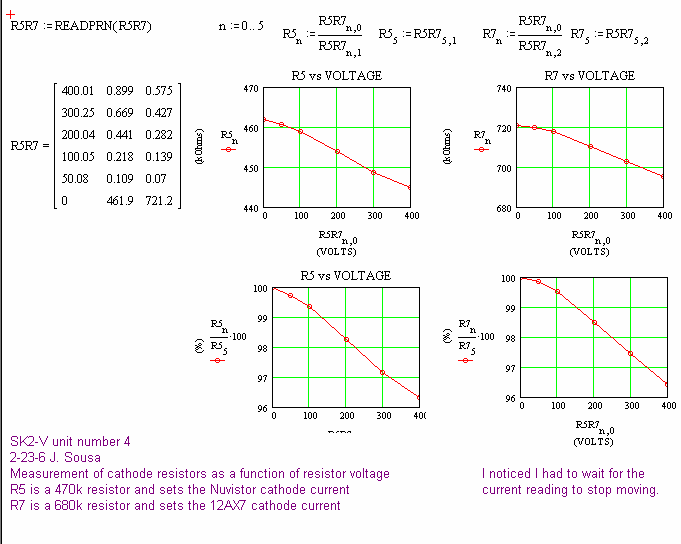
DC voltage measurements showed some inconsistencies that are explained by the voltage coefficient of the Allen Bradley carbon composition resistors.
When I shared my DC measurements of internal nodes with Bob Pease, he was mystified by the discrepancies from simple hand calculation. After all, he had been the product engineer for the SK2-V in the early 60's. His dissatisfaction with the discrepancy prompted me to investigate the voltage coefficient of the resistors.
The following plots show my measurements of this voltage coefficient for R5=470k and R7=680k in my hand-traced SK2-V schematic above.
